Crimping and Swaging Machine
Compression Fittings for RTP/TCP
Why Outer Compression?
Reinforced thermoplastic pipe cannot be joined in the same way as conventional steel pipe. Heat applied close to the pipe end can affect the thermoplastic liner and reinforcement, while the multilayer wall also requires controlled load transfer through the fitting.
Outer compression forms the metal sleeve directly around the pipe end. As the sleeve closes, the fitting profile engages the pipe wall and creates the mechanical retention required for the finished connection. The forming diameter depends on the fitting geometry and the construction of the pipe being assembled.
Crimping the fittings:
- Deformable metal sleeve – formed radially around the pipe during installation.
- Internal gripping profile – transfers mechanical load between the fitting and pipe wall.
- Sealing components – positioned within the joint according to the fitting design.

Crimping and Swaging
Crimping and swaging use different forming movements to install steel fittings on RTP and TCP pipe. Crimping closes segmented dies around the fitting, while swaging changes the fitting diameter through a more continuous radial forming process.
Goldstone supplies both machine types for pipe connection work. The swaging equipment shown on this page combines external compression and internal expansion in one machine, allowing the forming direction to be selected according to the fitting and pipe structure. This arrangement is particularly useful for larger pipe sizes and connection designs that require tighter control of deformation.
External Crimping
Internal Swaging
Crimping Machine
The crimping machine uses segmented hydraulic dies to form the fitting from the outside. The pipe and fitting are first positioned concentrically within the die set, allowing pressure to be applied evenly around the circumference.
During the forming cycle, the dies reduce the sleeve diameter until the fitting reaches the specified profile. Controlled die movement helps maintain consistent contact around the pipe end and limits local distortion of the metal sleeve. Once the target position is reached, the dies retract and the assembled connection can be removed for inspection.
- Pipe Dia.: 2-6 inch
- Clamping Force: 1300 ton
- System Pressure: 30 MPa

Crimping Machine

Pipe Positioning

Formed Fitting
Swaging Machine
Swaging forms the steel fitting through continuous radial movement rather than a series of discrete die impressions. This produces a smoother change in diameter and gives closer control over the final shape of the sleeve.
The machine shown here can work from either side of the fitting wall. External tooling reduces the fitting diameter around the pipe, while internal tooling expands the inner sleeve toward the surrounding wall. Both functions are built into the same machine platform, reducing the need to transfer large pipe assemblies between separate forming stations.
This forming range is useful when different pipe constructions require different deformation paths. Glass-fiber TCP, for example, has a narrower strain range than many conventional RTP structures, making forming control especially important around the reinforced layers.

External Compression Swaging
External compression acts directly on the outside of the steel sleeve. Radial tooling closes around the fitting and gradually reduces its diameter while the pipe remains centered through the forming area.
Tool position and final diameter are set according to the fitting profile rather than by pipe size alone. Sleeve thickness, pipe wall construction and the required contact geometry all influence the amount of forming applied during the cycle.


Internal Expansion Swaging
Internal expansion forms the fitting from inside the bore. The mandrel or expansion tool moves into the connection and enlarges the inner sleeve toward the surrounding pipe wall.
This direction of movement allows deformation to be introduced closer to the liner instead of relying entirely on pressure from the outside. Tool diameter and expansion travel can be adjusted around the fitting profile and the deformation limits of the pipe structure.


Workshop Swaging Machine
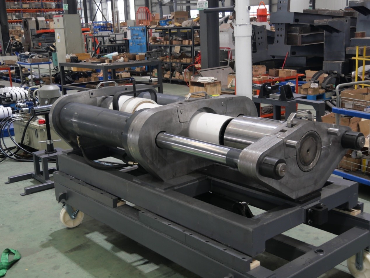
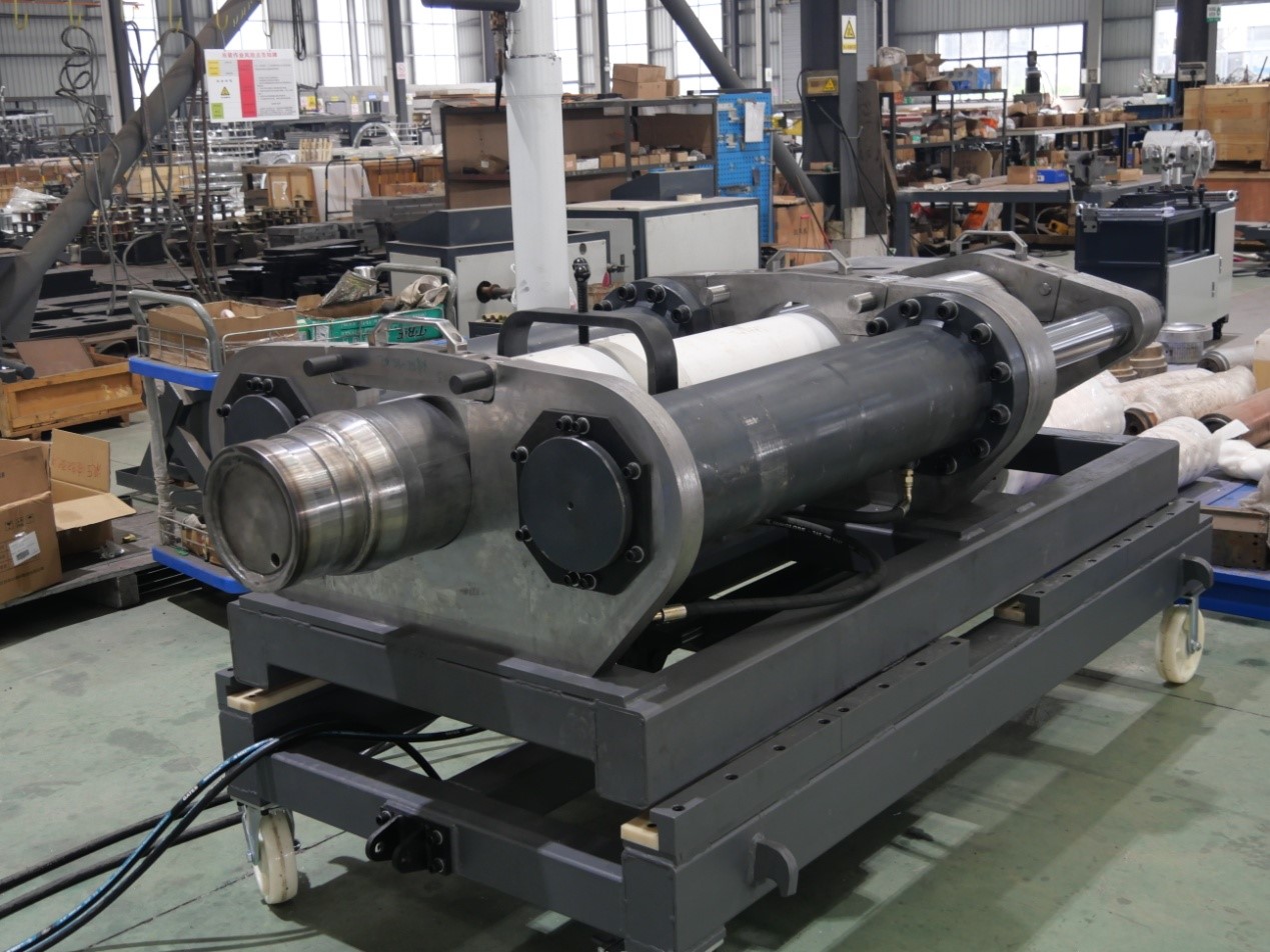
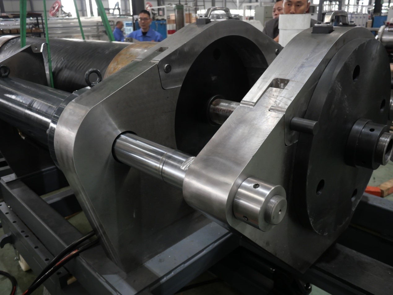
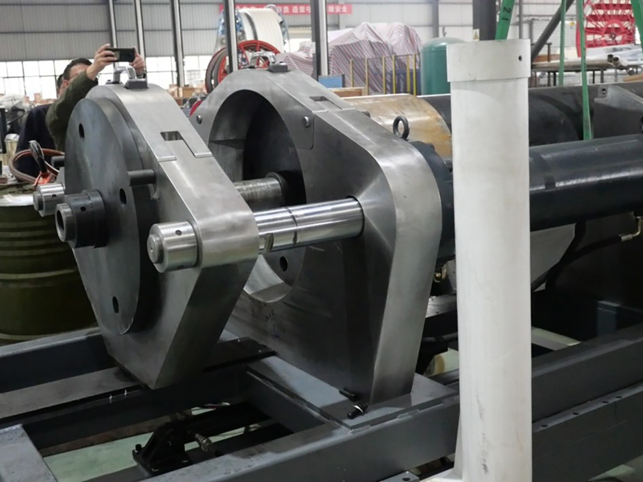
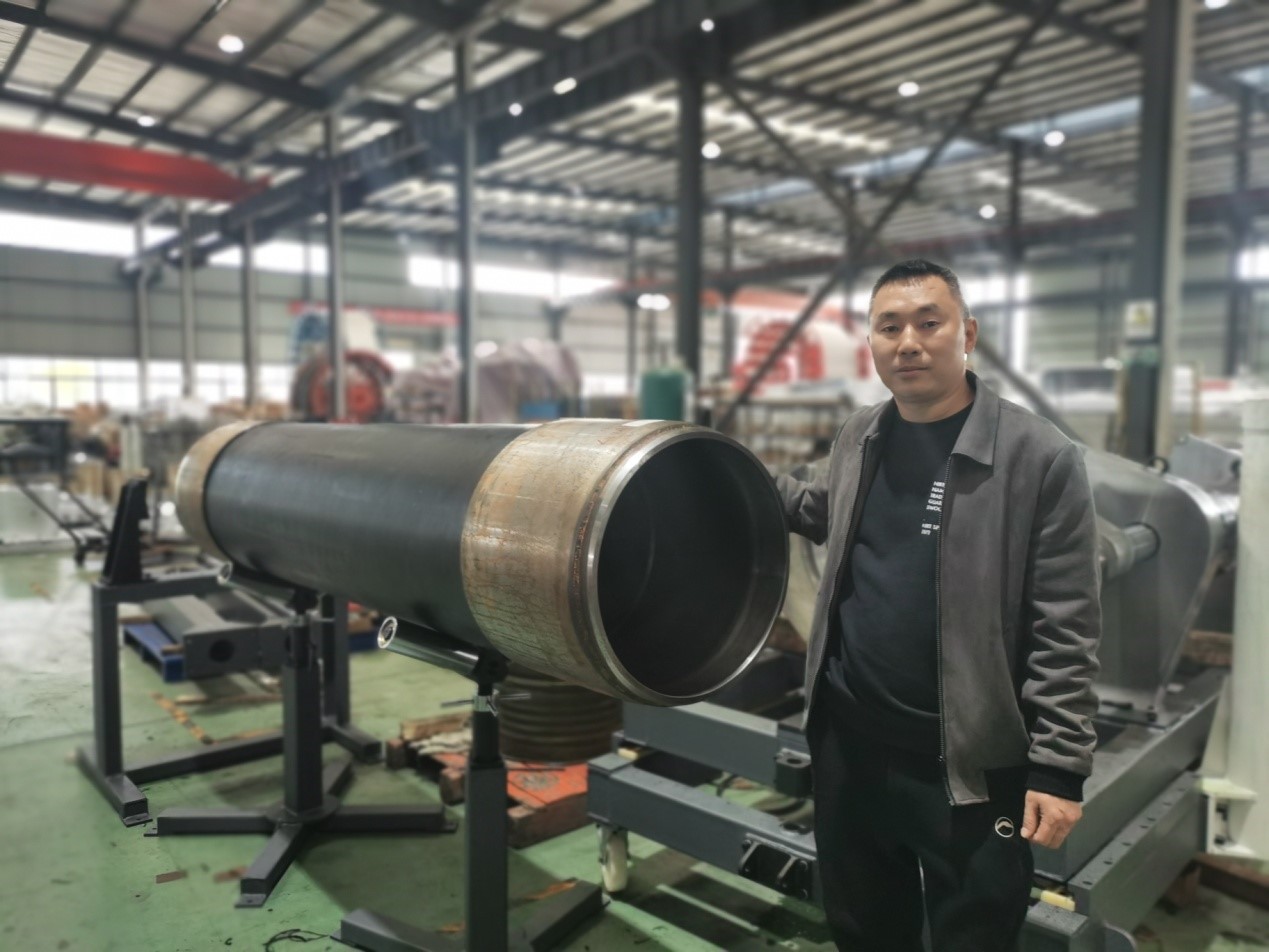
The workshop photographs show the larger swaging assembly from several working angles, including the hydraulic frame, forming area and pipe support arrangement. Full-size pipe sections can be positioned through the machine while the fitting remains accessible at the forming end.
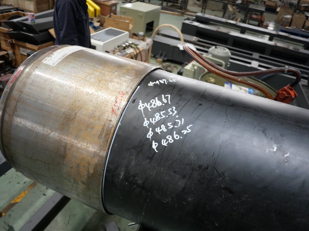
Several views also show trial assemblies with large-diameter pipe and steel sleeves. These images provide a practical reference for machine scale, pipe positioning and access around the connection during workshop operation.